
What Is a Single Stage Pump and How Does It Work?

A Single Stage Pump moves liquid through one impeller before discharge. Its design looks simple, but performance depends on details. Impeller diameter, shaft speed, casing shape, and system resistance all matter.

The U.S. Department of Energy reports that pumping systems can consume 25% to 50% of industrial facility energy. Its pump-system guidance also emphasizes correct sizing, throttling control, and maintenance. Hydraulic Institute standards provide reference methods for pump testing, efficiency, vibration, and application selection. Meanwhile, Grand View Research’s 2024 centrifugal pump analysis identifies strong demand from water treatment, building services, agriculture, and industrial processing. These reports describe market direction, not every installation. Real results still depend on field conditions.

A Single Stage Pump typically draws liquid through its suction nozzle. The rotating impeller adds velocity. The casing then converts much of that velocity into pressure. Picture water entering near the shaft and leaving along the casing’s outer edge. That path explains the pump’s basic operation.

Pump engineer Igor J. Karassik is widely credited with saying, “The pump is the heart of the system.” The comparison remains useful, though imperfect. A pump cannot compensate for blocked pipes, poor alignment, or an undersized motor. Engineers must examine the entire system, not just the pump curve. This guide will explain construction, operating principles, advantages, limitations, efficiency concerns, and practical selection criteria. It will also question a common assumption: simpler equipment is not always easier to operate well.
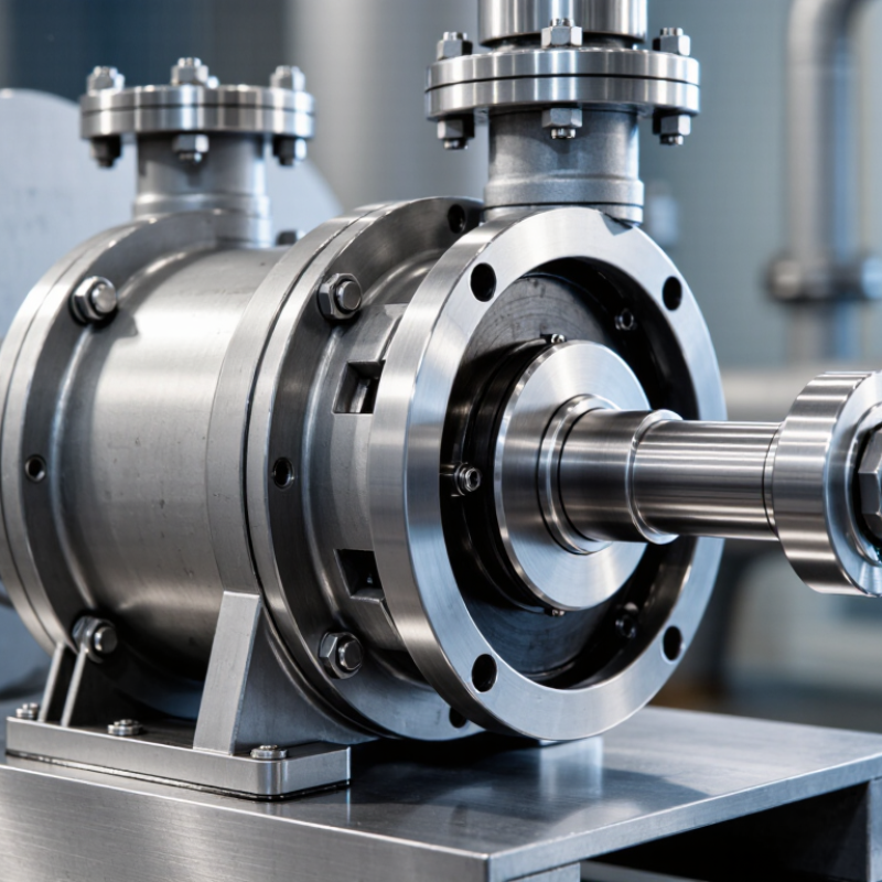
What Is a Single Stage Pump and How Does It Work?

Single-Stage Pump Definition: One Impeller for Low-to-Medium Head Service

What Is a Single Stage Pump and How Does It Work?

A single-stage pump uses one impeller to move liquid through a casing. This design provides low-to-medium head service for many water and process applications. As liquid enters the suction eye, the rotating impeller accelerates it outward. The casing then converts much of that velocity into pressure. Pressure rises. The discharge pipe carries the liquid toward the system.

Single-stage pumps are often chosen for circulation, drainage, irrigation, and general transfer duties. Their simple construction usually allows easier inspection and routine maintenance. A technician can check the shaft seal, bearings, coupling, and impeller without managing several impeller stages. However, the actual head depends on impeller diameter, speed, flow rate, and system resistance. A pump rated for 30 metres of head may deliver much less at a higher flow rate.

In field checks, a pressure gauge and flow reading reveal more than the nameplate alone. Unusual vibration, a rattling sound, or unstable discharge pressure may indicate cavitation, air entry, blockage, or incorrect sizing. Suction piping deserves careful attention. Small leaks can reduce performance before they become obvious. A single-stage pump cannot efficiently handle every high-rise or high-pressure duty. I would recheck the duty point before installation, because a convenient selection can still be wrong. Impeller wear also changes performance over time. That detail is easy to overlook.

Main Components: Impeller, Casing, Shaft, Seal, Bearings, and Motor

What Is a Single Stage Pump and How Does It Work?

A single-stage pump uses one impeller to move liquid from the suction side to the discharge side. The motor turns the shaft, and the shaft rotates the impeller inside the casing. As the impeller spins, its curved blades add velocity to the liquid. The casing then converts much of that velocity into pressure. This process supports water circulation, cooling systems, and many industrial duties.

Each component has a practical role. The impeller transfers energy to the liquid. The casing guides flow and contains pressure. The shaft carries torque from the motor to the impeller. A mechanical seal helps prevent leakage around the rotating shaft. Bearings support smooth rotation and control vibration. The motor supplies the driving power. Small alignment errors matter. They can create noise, heat, and early wear.

Tips: Check seal leakage, bearing temperature, and unusual vibration during operation. Keep the suction line clear and confirm the pump is properly primed. A dry start can damage the seal within minutes. Operators sometimes focus only on motor current, but that is not enough. Inspect the impeller for erosion and blockage, especially when the liquid contains fine particles. Maintenance records should include sounds, temperatures, and pressure readings. Some inspections are easy to overlook. That weakness deserves attention.

What Is a Single-Stage Pump and How Does It Work?

A single-stage centrifugal pump uses one impeller to transfer energy from the motor to the fluid. The motor rotates the shaft and impeller, the impeller increases fluid velocity, and the casing converts part of that velocity into pressure. The seal limits leakage around the shaft, while the bearings support smooth rotation.

Chart basis: This idealized comparison uses the centrifugal-pump affinity laws for the same impeller diameter, fluid, and efficiency: flow varies with speed, head varies with speed squared, and shaft power varies with speed cubed. Actual pump performance depends on the impeller design, casing, seal, bearings, motor, and operating conditions.

Operating Sequence: Suction, Impeller Acceleration, Pressure Rise, and Discharge

What Is a Single Stage Pump and How Does It Work?

A single-stage pump uses one impeller to move liquid and increase its pressure. The operating sequence begins at the suction inlet. As the impeller rotates, lower pressure forms near its eye, drawing liquid into the casing. The liquid should arrive steadily, without excessive air or turbulence. Even a small air leak can interrupt this action.

Inside the impeller, rotating blades accelerate the liquid outward. This creates velocity, not pressure alone. The casing then guides the fast-moving liquid through a volute or diffuser. As flow passage area increases, velocity decreases and pressure rises. The pressurized liquid reaches the discharge outlet and enters the connected piping. In field checks, unusual noise, vibration, or fluctuating discharge pressure often signals poor priming, restricted suction flow, or impeller wear. The sequence sounds simple. Real systems are less forgiving.

Tips: Confirm the pump is properly primed before operation. Keep the suction line short, sealed, and correctly sized. Check the rotation direction during commissioning. A pressure gauge near the discharge can reveal unstable performance. Do not judge efficiency from pressure alone; flow rate, temperature, liquid properties, and power demand also matter. Small installation details can change the entire operating result.

Key Performance Data: Flow, Head, NPSH, Speed, and 60–85% Efficiency

What Is a Single Stage Pump and How Does It Work?

A single-stage pump uses one impeller to add energy to liquid. The impeller spins inside a casing, converting motor power into flow and pressure. Flow describes volume moved, usually in m³/h or gallons per minute. Head measures the height or pressure the pump can develop, not simply distance. This distinction matters when pipe friction, valves, and elevation change the duty point.

Key Performance Data: Flow, Head, NPSH, Speed, and 60–85% Efficiency

Pump selection should begin with the actual operating point. Hydraulic Institute guidance emphasizes matching flow and head with the pump curve, rather than choosing maximum capacity. NPSH available must exceed NPSH required, with practical margin against cavitation. Cavitation can sound like gravel inside the casing and damage the impeller quickly. Speed also changes performance sharply. Under the affinity laws, flow varies with speed, while head changes approximately with speed squared. The U.S. Department of Energy’s Improving Pumping System Performance sourcebook identifies proper sizing and system control as major efficiency opportunities. Well-selected centrifugal pumps may operate around 60–85% efficiency, but this range is not guaranteed.

Tips: Record pressure at suction and discharge, then calculate real head. Check liquid temperature and elevation before trusting a catalog curve. Keep a maintenance log. One mistake remains common: a clean spreadsheet can still describe the wrong system. Field readings may expose that uncomfortable gap. A variable-speed drive can help, but throttling losses and minimum-flow requirements still need review.

Selection Standards: BEP Operation, Cavitation Control, and ISO 9906 Testing

What Is a Single Stage Pump and How Does It Work?

A single-stage pump uses one impeller to convert motor power into fluid pressure. Liquid enters the impeller eye, accelerates outward, and leaves through the casing. Its simple structure supports easier maintenance and reliable service in water, cooling, and process systems. However, “simple” does not mean automatically efficient. The U.S. Department of Energy reports that pumping systems can account for about 25% of industrial electricity use, making selection errors expensive.

Selection should begin near the best efficiency point, or BEP. Operation far left can cause recirculation, vibration, and heat. Operation far right may overload the motor and increase seal stress. Cavitation control requires checking NPSH available against NPSH required, including pipe losses, liquid temperature, and site elevation. A practical mistake is trusting catalog conditions without measuring the actual suction pressure. Field conditions often disagree.

Tips: Keep the operating point close to BEP, but do not force it blindly. Review the complete system curve. Leave a sensible NPSH margin, then verify it during commissioning. For acceptance, ISO 9906:2012 provides recognized procedures for testing flow, head, power, and efficiency. Record fluid temperature and speed. The Hydraulic Institute also recommends testing under defined, repeatable conditions. Small measurement errors can change the decision. I have seen a pump pass a shop test yet underperform onsite because the suction line was undersized. That detail deserves more attention.

What Is a Single Stage Pump and How Does It Work? - Selection Standards: BEP Operation, Cavitation Control, and ISO 9906 Testing

Selection Dimension Typical Data or Requirement Engineering Interpretation
Pump Configuration One impeller and one main pressure-rise stage A single-stage pump is generally selected for low-to-moderate head duties. Multiple stages are used when substantially higher discharge pressure is required.
Operating Principle Rotating impeller converts shaft power into fluid velocity; the casing converts part of that velocity into pressure The pump increases fluid energy through centrifugal action, followed by velocity recovery in the volute or diffuser.
Typical Applications Water transfer, HVAC circulation, irrigation, process services, cooling systems, and general industrial fluid handling The selected construction must match the fluid temperature, viscosity, solids content, corrosiveness, and required operating pressure.
Rated Flow and Head Example duty point: 100 m³/h at 45 m total dynamic head The duty point should be established from the system curve, including static lift, friction loss, fittings, control valves, and required terminal pressure.
Best Efficiency Point (BEP) Preferred continuous operation: approximately 80–110% of BEP flow, unless the pump manufacturer specifies another range Operation near BEP normally reduces hydraulic losses, shaft deflection, vibration, seal loading, and energy consumption.
Allowable Operating Region A common preliminary screening range is about 70–120% of BEP flow This is a screening guideline, not a universal limit. The final allowable range must come from the certified pump curve and service conditions.
Efficiency at Selected Duty Illustrative target for a medium-size clean-water pump: approximately 70–85% Actual efficiency depends on pump size, speed, impeller diameter, fluid properties, and operating point. Use the certified performance curve for final selection.
Cavitation Control NPSHA must exceed NPSHR with an appropriate margin NPSHA is determined by the installation and liquid conditions; NPSHR is supplied from pump testing. A common preliminary margin is 10% or at least 0.5 m, subject to project requirements.
Cavitation Warning Signs Crackling or gravel-like noise, unstable flow, vibration, reduced head, and impeller pitting Corrective actions may include reducing suction losses, increasing liquid level, lowering liquid temperature, reducing speed, or selecting a pump with lower NPSHR.
Speed Selection Typical motor speeds: approximately 1,450 or 2,900 rpm at 50 Hz; approximately 1,750 or 3,500 rpm at 60 Hz Lower speed generally reduces noise, wear, and NPSH demand but may require a larger pump. Actual synchronous and running speeds depend on motor design and slip.
Fluid Compatibility Confirm temperature, viscosity, density, pH, chloride level, solids concentration, and vapor pressure Material selection must cover the casing, impeller, shaft, wear components, elastomers, and mechanical seal.
Motor Power Check Hydraulic power: Ph = ρgQH; shaft power: Ps = Ph/η For 100 m³/h, 45 m head, and 78% pump efficiency, hydraulic power is about 12.3 kW and shaft power is about 15.8 kW. Motor selection should include appropriate service margin.
ISO 9906 Testing Hydraulic performance testing for rotodynamic pumps, including flow, head, power, and efficiency measurements The applicable acceptance grade and tolerances should be agreed in the purchase specification before testing.
ISO 9906 Test Conditions Controlled test speed, stable suction conditions, calibrated instruments, and recorded fluid properties Test results are meaningful only when measurement uncertainty, instrument calibration, and test installation conditions are documented.
Performance Acceptance Compare measured duty-point head, flow, power, and efficiency with the contractual guarantee Acceptance should use the agreed ISO 9906 procedure and tolerance grade rather than an informal comparison with a catalogue curve.
Control Method Variable-speed control, throttling, bypass control, or impeller trimming Variable-speed control can improve energy performance for changing demand, while throttling changes the system operating point but does not eliminate excess pump head.
Final Selection Checklist Duty point, BEP location, NPSH margin, efficiency, motor rating, materials, seal arrangement, test requirements, and lifecycle cost Select the pump from verified performance data and confirm that normal, minimum, maximum, and start-up conditions remain within safe operating limits.

Note: Numerical ranges shown are general engineering screening values. Final limits, guarantees, and acceptance criteria must be confirmed against the project specification, certified pump curve, fluid data, and agreed ISO 9906 test procedure.