How to Choose the Right Electrical Wiring for Your Project?

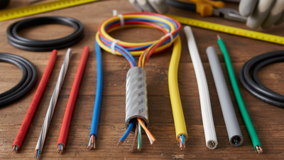
Choosing the right electrical wiring is a practical decision that affects safety, performance, and future maintenance. The correct cable must match the circuit’s voltage, expected load, installation method, and surrounding environment. A wire running inside a dry wall needs different protection from one exposed to moisture, heat, chemicals, or outdoor sunlight.

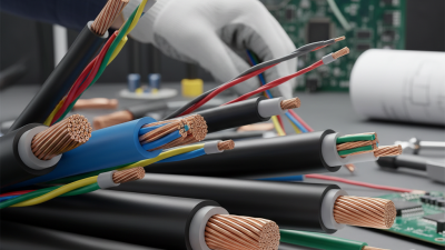
Wire size matters. An undersized conductor can overheat, damage insulation, and create a serious fire risk. An oversized cable may cost more and complicate installation without improving the circuit. Electricians commonly check the current rating, allowable voltage drop, insulation temperature, and distance before selecting a conductor. Copper is widely used for its conductivity and reliable connections, while aluminum may require compatible terminals and careful installation.

Small details matter.

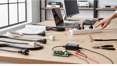
This guide explains how to compare common electrical wiring types, including solid and stranded conductors, building cable, flexible cord, and wires installed in conduit. It also considers grounding, color identification, circuit protection, and local electrical codes. Requirements can vary by country, building type, and application, so manufacturer instructions and authoritative standards should guide every final choice. A qualified electrician should inspect unfamiliar or high-load work.

There is no universal “best” wire. The best option depends on the project. In practice, planning is sometimes rushed, and that is where mistakes begin. Measuring the route, checking the load, and leaving room for inspection can prevent expensive corrections later. This article offers a careful starting point, while recognizing that real installations may reveal details a simple checklist misses.
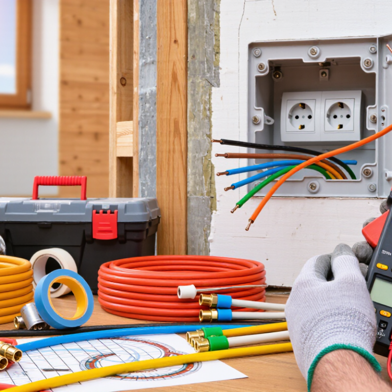
How to Choose the Right Electrical Wiring for Your Project?

Calculate Load Current with NEC 125% Continuous-Load Sizing

How to Choose the Right Electrical Wiring for Your Project?

Continuous loads change the calculation. Under the 2023 National Electrical Code, continuous loads must be sized at 125% of their expected current. A load running for three hours or longer often qualifies. For example, a 40-amp continuous EV charger requires a circuit rated for at least 50 amps. The conductor must also meet the required ampacity after temperature and bundling adjustments. A larger breaker alone does not solve an undersized wire.

Real projects are less tidy than drawings. An electrician may find warm attic spaces, crowded conduit, or terminals with weak connections. These details can reduce safe capacity. NFPA 70, Article 210.20(A), addresses overcurrent protection, while Table 310.16 provides conductor ampacity values under stated conditions. The U.S. Energy Information Administration reported that residential electricity use averaged about 10,500 kWh per household in 2020. More electric heating, cooking, and charging can increase branch-circuit demand. I have seen load schedules fail because “typical use” replaced measured demand. That shortcut needs reconsideration.

Tips: List continuous and noncontinuous loads separately. Multiply continuous current by 1.25. Check ambient temperature, conductor material, insulation rating, conduit fill, and voltage drop. Confirm the final design with the locally adopted electrical code and a qualified electrician. A 50-amp circuit may still need larger conductors when the installation conditions are severe.

Select Conductor Ampacity from NEC Table 310.16 at 75°C

How to Choose the Right Electrical Wiring for Your Project?

Choosing conductor ampacity is more than matching wire size to a breaker. NEC Table 310.16 provides allowable ampacities under specific conditions. Its 75°C column applies when the conductor insulation and equipment terminations are rated for 75°C. Always verify the terminal markings before using this column. Some equipment still requires the 60°C rating, especially in smaller installations.

Start by identifying the conductor material, insulation type, and wire size. Then read the copper or aluminum section of Table 310.16. The table assumes no more than three current-carrying conductors in a raceway, cable, or earth, with a 30°C ambient temperature. Real projects can differ. More conductors may require adjustment, while hot spaces may require correction. I have seen plans fail because the installer checked only the table and ignored the surrounding conditions.

Do not stop at the table value. Compare the conductor ampacity with the overcurrent protection requirements and equipment ratings. The final ampacity may need to be limited by the lowest-rated component. Small conductors also have special protection rules that can override a simple table lookup. Measure the installation space carefully. Recheck every assumption. A clean calculation on paper can still be wrong when the cable runs beside hot equipment or through a crowded raceway.

Compare Copper’s 1.68 μΩ·cm and Aluminum’s 2.82 μΩ·cm Resistivity

How to Choose the Right Electrical Wiring for Your Project?

Copper has a resistivity of 1.68 μΩ·cm at about 20°C. Aluminum measures 2.82 μΩ·cm. This means aluminum offers roughly 68% more resistance at the same length and cross-sectional area. In practical terms, it can create greater voltage drop and heat. A long cable feeding a workshop may show this difference clearly under heavy load.

I check conductor length, expected current, installation temperature, and allowable voltage drop before choosing a wire. The basic relationship is simple: resistance rises with resistivity and length, but falls as conductor area increases. Aluminum can therefore work well when its larger size is correctly designed. It is also lighter, which may help on long routes.

Terminations need care.

Aluminum connections can experience oxidation, thermal expansion, and gradual loosening. Approved lugs, suitable joint compounds, and correct tightening methods matter. Copper is usually more forgiving, but it still needs clean, secure connections. I have seen wire selected by price alone, then reconsidered after a warm terminal appeared during inspection. That decision was too narrow. Resistivity is important, yet installation quality, local electrical codes, insulation rating, and future load deserve equal attention. Temperature also changes resistance, so a laboratory value should not be treated as a fixed field result.

Check Voltage Drop Against the 3% Branch-Circuit and 5% Total Limits

How to Choose the Right Electrical Wiring for Your Project?

Check Voltage Drop Against the 3% Branch-Circuit and 5% Total Limits

Voltage drop is easy to underestimate during project planning. The National Fire Protection Association’s NFPA 70, 2023 edition, recommends limiting branch-circuit voltage drop to 3%. It also recommends keeping feeder and branch-circuit drop within 5% total. These are performance guidelines, not universal installation mandates.

Consider a 120-volt circuit carrying 20 amps. A 60-foot one-way run creates 120 feet of conductor length. Using approximately 1.588 ohms per 1,000 feet for 12 AWG copper, the estimated drop reaches 3.8 volts. That equals about 3.2%. The circuit slightly exceeds the branch-circuit target. Actual results can change with conductor temperature, connections, conduit layout, and motor starting current. A tidy calculation may still mislead.

Tips: Measure the complete circuit path, not only the visible distance. Include both outgoing and returning conductors. Use the load’s highest expected current. Check the conductor’s resistance and installation temperature. For sensitive equipment, leave design margin below 3%. NEC Chapter 9 tables provide useful impedance data, while field testing can reveal loose terminals or unexpected heating. I would not rely on wire size alone. Even a short run can suffer noticeable drop when the load is large.

Verify Insulation Ratings, Conduit Conditions, and Local Code Requirements

Choosing electrical wiring starts with insulation, not color or convenience. The conductor must suit the circuit’s voltage, current, temperature, and installation environment. Check its insulation rating for dry, damp, or wet locations. Many wiring failures begin when moisture exposure is underestimated. The National Fire Protection Association reported about 35,150 home fires involving electrical distribution and lighting equipment annually from 2015 to 2019. That figure deserves attention.

Inspect the conduit before pulling conductors. Look for crushed sections, sharp edges, rust, standing water, and blocked fittings. Conduit fill also matters. Overcrowding can increase heat and damage insulation during installation. Confirm conductor ampacity after applying ambient-temperature and bundling adjustments. A higher temperature rating does not automatically permit a larger breaker. This is easy to misunderstand.

Local code requirements must control the final selection. Verify conductor markings, grounding methods, box volume, support spacing, and required protection devices. The National Electrical Code provides a technical baseline, but local authorities may adopt different editions or amendments. Ask the permitting office before purchasing materials. A careful installer records cable types, insulation ratings, conduit measurements, and inspection notes. One practical lesson is uncomfortable: a visual check can look complete while missing a wet-location requirement. Rechecking the schedule and site conditions takes minutes. It can prevent expensive rework and serious hazards. Sources: NFPA, Home Structure Fires report; NFPA 70, National Electrical Code.

How to Choose the Right Electrical Wiring for Your Project? - Verify Insulation Ratings, Conduit Conditions, and Local Code Requirements

Project Checkpoint What to Verify Typical Requirement or Reference Suitable Wiring Choice Important Limitations
Indoor, dry location Check whether the cable or conductor is listed for dry locations and whether the insulation voltage rating is adequate. Common building-wire insulation ratings include 600 V. The wiring method must also be permitted by the applicable electrical code. Listed insulated conductors installed in an approved raceway, or a cable assembly permitted for the location. Do not use a dry-location-only product where condensation, water, or damp conditions may occur.
Damp or wet location Confirm that the conductor insulation and the complete wiring method are identified for wet or damp exposure. A wet-location listing is required where water may enter or accumulate in the raceway or wiring space. Conductors marked for wet locations, such as insulation with a wet-location designation, installed in a suitable raceway. Raceways installed outdoors or underground may be treated as wet locations because condensation can form inside them.
Temperature exposure Review the conductor temperature rating, ambient temperature, terminal rating, and number of current-carrying conductors. Equipment terminations commonly limit the usable ampacity to the rating permitted by the applicable code and equipment marking. Use insulation suitable for the highest expected temperature and apply all required correction and adjustment factors. A higher insulation temperature rating does not automatically permit higher circuit ampacity at the terminals.
Copper conductor ampacity reference Compare the calculated load with the allowable ampacity after derating and termination limits. Typical 75°C ampacities for copper conductors in a common code ampacity table: 14 AWG = 20 A, 12 AWG = 25 A, 10 AWG = 35 A, 8 AWG = 50 A. Select the conductor size based on calculated load, overcurrent protection, installation conditions, and local code requirements. These values are reference ampacities, not a universal sizing recommendation. Small-conductor rules and terminal limitations may reduce the allowable value.
Conduit condition Inspect the raceway for corrosion, cracks, sharp edges, blocked passages, water accumulation, and physical damage. The raceway must be listed for the environment and installed to protect conductors from mechanical damage. Use a corrosion-resistant, mechanically suitable raceway with compatible fittings and properly protected entries. Damaged or corroded conduit can compromise insulation and bonding continuity; repair or replace it before pulling new conductors.
Conduit fill Calculate the total conductor area and compare it with the permitted raceway fill percentage. For a typical raceway containing three or more conductors, the maximum fill is commonly 40%; different limits apply to one or two conductors. Choose a raceway size that allows compliant fill and practical conductor installation. Do not rely only on nominal conduit size. Account for conductor insulation diameter, grounding conductors, and internal fittings where required.
Bends and pulling access Check the total bend between pull points and verify that boxes or fittings provide sufficient pulling space. Many code systems limit the total bend between pull points to 360 degrees unless additional access is provided. Use properly spaced pull boxes, accessible junction boxes, and long-radius bends where appropriate. Excessive pulling force can damage insulation even when the conductor size and ampacity are correct.
Voltage drop Calculate voltage drop using circuit length, load current, conductor material, and conductor size. A commonly used design target is no more than 3% voltage drop on a branch circuit and no more than 5% for the combined feeder and branch circuit. Increase conductor size or reduce circuit length when the calculated voltage drop is excessive. Voltage-drop targets may be recommendations rather than mandatory limits, depending on the jurisdiction and equipment requirements.
Outdoor or underground installation Verify wet-location suitability, burial depth, physical protection, drainage, and protection from sunlight where applicable. Underground raceways are generally treated as wet locations. Burial depth and protection requirements vary by wiring method and local code. Use wet-location-rated conductors and a raceway or cable assembly approved for the installation conditions. Seal or drain raceways as required; do not assume that a watertight appearance eliminates internal condensation.
Overcurrent protection Match the breaker or fuse to the conductor ampacity, connected load, equipment rating, and code requirements. Overcurrent protection must prevent conductor overheating under expected operating conditions. Select conductor size and protective device together after completing the load calculation. A larger conductor does not justify a larger breaker unless the complete circuit and equipment are rated for it.
Local code and permits Confirm the adopted electrical code edition, permit requirements, inspection process, and any local amendments. Requirements can differ by country, state, province, municipality, building type, and installation environment. Use products and wiring methods recognized by the authority having jurisdiction. Manufacturer instructions, inspection requirements, and local amendments may be stricter than general reference tables.
Final safety verification Check conductor identification, grounding and bonding, torque requirements, insulation integrity, labeling, and test results. The completed installation should be inspected and tested in accordance with the applicable code and project requirements. Have installation and verification completed by a qualified electrician where required. De-energize circuits before work and verify absence of voltage with an appropriate test instrument.

Note: The values shown are general design references. Always confirm the current electrical code, local amendments, equipment labeling, and project-specific conditions before selecting or installing electrical wiring.